In Article 4: Basics of Powering a Layout, we examined different methodologies for wiring the DCC system and providing power to the track. One item briefly suggested in the previous article was to build a test layout. This article will expand on that theme outlining benefits of building a test layout before starting you main layout. The article will provide some suggested test layouts. For the first design, the article shows how to split the layout into occupancy blocks. For the others, readers are encouraged to develop their own diagram dividing it into blocks. (We will be happy to review and comment on your diagrams of these layouts if that would be helpful.)
The primary purpose of a test layout is to provide a learning opportunity for understanding DCC before implementing it on your main layout. However, the benefits of a test layout are not over with the implementation of DCC on your main layout. Once your layout is running, the test layout provides an opportunity to try new ideas, DCC equipment, or locomotives in a small and controlled environment. Another suggestion is to use a loop based layout (much easier in N scale) so that it can be used to break in new locomotives. Also, a test layout is very beneficial for programming locomotive; it eliminates the potential for accidentally reprogramming the rest of your locomotives as you can safely program settings in Ops mode. We especially like to program locomotives’ speed tables on our test layout.
Test Layout Designs
Our favorite idea for a test track is a loop of track with at least one passing siding and a spur. The ability to have continuous running is not required for a test track, but helps significantly with alternative uses for the test track. A good design is the Montandon Branch featured in Model Railroader’s Great Model Railroads -2002. The track play is available in the Track Plan Database (Subscriber Only) portion of the Model Railroader web site. If you are not subscriber, Kato has published a very similar plan, the Granny Kay & Bonnie which is available on their web site. This is the plan we use for the current DCC by Design N scale test track. A good HO track plan for a loop style test track is Atlas Plan #10013 simple oval with spurs.
While a loop is our favorite style test track, it can be hard to find the space for this type of test track in the larger scales. Therefore, we offer a couple of suggestions for shelf style test tracks.
- Wingate track plan from Tony Koester’s Realistic Model Railroad Operations.
- PE "Orphan Branch" track plan from LayoutVision’s Layout Design Gallery
- San Hose Shelf Switcher also from LayoutVision
- Fairweather Branch Line from Micro Layout Design Gallery
Another module with all of the elements needed to be a good DCC test track is the Timesaver, John Allen's Classic switching puzzle. We will examine a modified version with a small yard to store a couple of different trains. This was my first DCC test track
Design #1 – GK&B
The loop of track design is one of the simplest, but with a few additions, it provides an excellent test layout. Below is the track diagram for the loop of track.
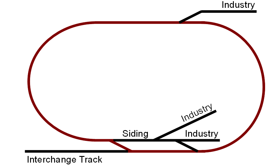
As can be seen above, the loop provides a passing siding on one side and several spurs for industry. The mainline route is shown in red. This arrangement provides the basic elements needed to test most facets of DCC including: power management, block detection, power wiring, programming track, turnout control, and signaling. One aspect that cannot be tested with this arrangement is reversing loops using DCC.
For this article, we will apply the power management techniques from Article #4 and develop the power wiring diagram for this layout. Turnout control & signaling are complex subjects and will be addressed in their own articles.
Power Management - The GK&B has no staging tracks, which significantly limits the number of locomotives, and thus current draw of the layout. The layout is best suited to a single local train arriving at the front of the track and performing all of the switch operations, then departing to the back of the track. Conceivability these duties could be separated into a through train dropping the cars for the town switcher to route, thus requiring two locomotives. A third could be added as the locomotive from the interchanging railroad; all it would do is move back and forth on the interchange track.
Thus the worst case is three locomotives on the layout with one switching and one running at the same time. Using the information from Article #4 the current draw would be about XXX amps. As described in Article #1, this is well within the maximum current rating of the starter systems from the major DCC vendors; Digitrax, NCE, and Lenz.
Circuit Breakers – Since the layout is too small to support multiple operators, there is not a need to separate the layout into power blocks to prevent a derailment of one train shutting down other operating trains. Also, since the single booster of the starter kit is not outputting more than 5 amps, circuit breakers are not required to limit the current draw in any one section of the layout. Finally, the layout is sufficiently small that trouble shooting the DCC system would not be a tedious affair; it is not worthwhile to provide isolation sections to simplify deciding where to start looking for a short. Therefore, we would not provide additional circuit breakers. (The starter kits include a main breaker for the entire layout.)
DCC Voltage & Amperage measurement – The layout is not anticipated to have significant amperage drawn from numerous locomotives, therefore, we would not recommend providing a permanent measurement device like the RRampMeter for this layout.
Block Detection –Layout Block Detection has two primary uses, display track occupancy for hidden track and/or for use in signaling system. (There are a variety of uses for local block detection, but that is a topic for another article.) If you plan to use block detection for either of these purposes, then you should include them on your test layout.
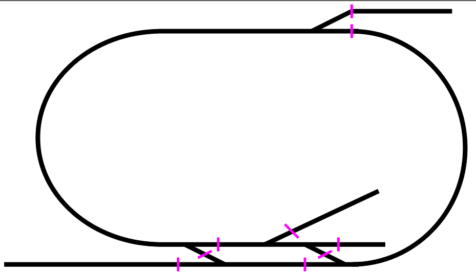
Since the GK&B will be used to demonstrate signaling, it needs block detection. The figure below shows the recommended block arrangement for the layout.
Power Wiring – Now that the power management and block detection have been developed, the power wiring arrangement can be developed. Since there is only one power district, Rail B does not need to be isolated. Rail A needs to be gapped at the ends of the blocks as identified above. (If you are unsure about how to cut these gaps, then we suggest our article Creating Rail gaps for Power Districts and Block Detection.) Each block needs at least one feeder, for large layouts more than one feeder is recommended. Because the blocks in this layout are small, only one feeder is provided per block. Below is the resulting power wiring diagram.
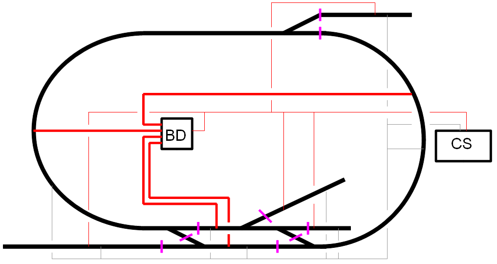
In the figure above, the layout in broken into four detection blocks, with Rail A insulated at each block separation (shown in red). The red lines show the detected block rail wiring (rail with insulators) and the individual block wires returning the detection unit (in this case a Digitrax BD4). The gray lines show the common rail wiring bus with one feeder for each block. (Note: the common rail would not be insulated.)
Programming Track – All DCC layouts need a programming track and there are several ways of incorporating programming tracks (Our suggested methods are described in our article Programming Track Design & Wiring.) For the GK&B, the programming track is made by a simple isolation of on spur; we have selected the interchange track because this layout is operated predominately from the front side. The programming track needs both the A & B rail to be isolated from the rest of the layout.
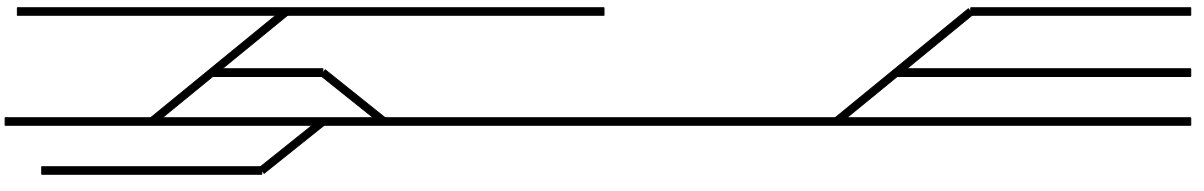
Design #2 - Wingate
The Wingate track plan was published by Kalmbach books in Realistic Model Railroad Operations by Tony Koester. I highly recommend this book for someone building a new layout or moving to operations focused layout. Using this design as a DCC test layout is a great way to combine learning DCC and learning about railroad operations. Building the modified version as shown below was my second testing layout and was my own approach for learning about operations.
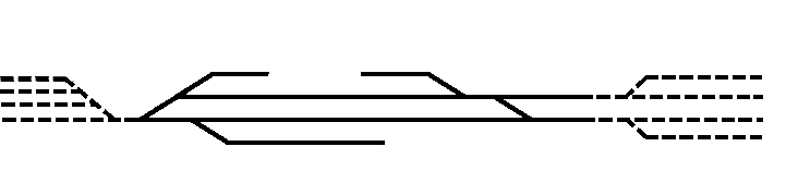
The dotted lines denote staging track while the solid lines are the active layout. Using the analysis process above and the K&B as a guide, develop the power wiring diagram for this layout.
To review the process:
- Consider that maximum number of locomotives on the layout and the number operating at once. Using Article #4, size your booster according to the resulting electrical load (amps.)
- Determine, based on operational profile, electric load, and complexity of trouble shooting whether to add circuit breakers. If so, mark with double vertical lines (like programming track for the GK&B) the ends of the power district(s).
- Determine the mainline route. Label it on the drawing.
- Determine if block detection will be used. (For this exercise, assume it will.) Mark on this diagram the ends of the blocks with a single vertical line. This is where the insulators should be placed in Rail A.
- Locate the feeder wire track connection locations for Rail A and Rail B. Mark them with the appropriate colored dot
- Draw the feeder and bus wires to the block detection unit and Command Station &/or Boosters.
- Select a track for the programming track. Mark the connection to the rest of the layout with double vertical lines (like programming track for the GK&B)
Design #3 - Timesaver
The Timesaver was developed by John Allen as a switch puzzle and not indicative of real operations. For the purposes of testing DCC, the timesaver is excellent, because is compresses a complex track arrangement into a very small space. Below is the track plan for a modified version of the time saver that includes a yard for a couple of trains. You are on your own for this design.
 Today we posted information about our

